Sfd Bmd Formula : Shear Force Diagram Of A Simply Supported Beam With Triangular Load Distribution Engineering Stack Exchange - Sfd, bmd for cantilever beams, simply supported beams and overhanging beams considering point loads, udl, uvl, couple.
Sfd Bmd Formula : Shear Force Diagram Of A Simply Supported Beam With Triangular Load Distribution Engineering Stack Exchange - Sfd, bmd for cantilever beams, simply supported beams and overhanging beams considering point loads, udl, uvl, couple.. Plotting sfd and bmd in one single graph for different conditions of the beams, such as cantilever with udl load, cantilever with the point loads akshay kumar (2020). • determine reactions at supports. Centroid of trapezium can be determine by using formula h/3((b+2a)/(b+a)). However, values of sf and bm are substantiated at the support if support reactions are identified. Sfd, bmd for cantilever beams, simply supported beams and overhanging beams considering point loads, udl, uvl, couple.
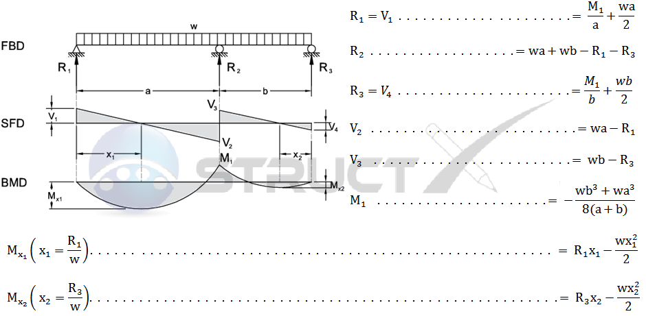
The advantage of plotting a variation of shear force f and bending moment m in a. Problem 1 based on sfd and bmd part 1 video lecture from shear force & bending moment in beams chapter of strength of materials subject for all engineering students. Fig:6 formulas for finding moments and reactions at different sections of a simply supported beam having udl at right. According to bis, the standard symbols used for sketching sfd are point load. Sfd and bmd can be blueprinted devoid of ascertaining support reactions as it is a cantilever beam.
Shear Force And Bending Moment Diagrams Notes For Mechanical Engineering Ese Gate Me from gs-post-images.grdp.co Bmd stands for bending moment diagram. Hence, sfd and bmd reduce the probability of the structure's failure. Sfd and bmd for different types of load. Sfd and bmd plays an important role in the design of a beam based on strength criterion. However, values of sf and bm are substantiated at the support if support reactions are identified. Strength of material or mechanics of solid The diagram which shows the variation of shear force 26 example problem 2 2. Draw sfd and bmd for the double side overhanging beam subjected to.
If a calculate the bending moment that results at the supports and i am looking for a formula to find the maximum bending moment for a trapezoidal loading, can.
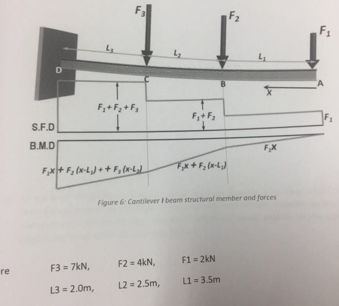
Distributed loads on beams (part 2) sfd and bmd diagram of cantilever beam. Axial force diagrams come additionally for column design. Text of bmd and sfd. Problem 1 based on sfd and bmd part 1 video lecture from shear force & bending moment in beams chapter of strength of materials subject for all engineering students. The above beam design formulas may be used with both imperial and metric units. Bmd stands for bending moment diagram. Shear force diagram (sfd) & bending moment diagram (bmd) form the basis for design of beams in general. Lecture 23 and 24 procedure for drawing shear force and bending moment diagram:preamble: .sfd and bmd for a simply supported beam subjected to three point loads as shown in the fig determine the absolute maximum bending moment and shear forces and mark them on sfd and bmd. Sfd stands for shear force diagram. Centroid of trapezium can be determine by using formula h/3((b+2a)/(b+a)). Here we discuss sign convention for sfd & bmd, different types of beams like simply supported beams, cantilever beams, propped cantilever beams and continuous beams. Sfd and bmd can be blueprinted devoid of ascertaining support reactions as it is a cantilever beam.
Distributed loads on beams (part 2) sfd and bmd diagram of cantilever beam. Welcome to our free online bending moment and shear force diagram calculator which can generate the reactions, shear force diagrams (sfd) and bending moment diagrams (bmd) of a cantilever beam. Strength of material or mechanics of solid Bending moment diagram (bmd) shear force diagram (sfd) axial force diagram. Bmd table for some standard cases some important guidelines.
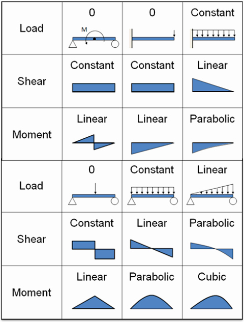
Continuous Beam Two Unequal Span With Udl from structx.com Sfd and bmd for different types of load. So my question now is about the bmd: How do point loads and udl be represented in sfd? Fig:4 sfd and bmd for simply supported at midspan udl carrying beam. Bmd table for some standard cases some important guidelines. E = modulus of elasticity, psi or mpa. If a calculate the bending moment that results at the supports and i am looking for a formula to find the maximum bending moment for a trapezoidal loading, can. The advantage of plotting a variation of shear force f and bending moment m in a.
How do point loads and udl be represented in sfd?
(d) simply supported beam with point load not at midspan let the beam ab of span l as in figure below carry a concentrated load. So my question now is about the bmd: Fig:4 sfd and bmd for simply supported at midspan udl carrying beam. A) simple lines and curved lines b) curved answer: By using formula, centroid of trapezium can be easily determined How do point loads and udl be represented in sfd? Problem 1 based on sfd and bmd part 1 video lecture from shear force & bending moment in beams chapter of strength of materials subject for all engineering students. Fig:6 formulas for finding moments and reactions at different sections of a simply supported beam having udl at right. Sfd and bmd for different types of load. Sfd and bmd can be blueprinted devoid of ascertaining support reactions as it is a cantilever beam. However, values of sf and bm are substantiated at the support if support reactions are identified. Bending moment diagram (bmd) shear force diagram (sfd) axial force diagram. Centroid of trapezium can be determine by using formula h/3((b+2a)/(b+a)).
Lecture 23 and 24 procedure for drawing shear force and bending moment diagram:preamble: Sfd and bmd for simply supported beam (udl and point load). The graphical representation of the bending moment is known as bmd (bending moment diagram). Sfd and bmd can be blueprinted devoid of ascertaining support reactions as it is a cantilever beam. Hence, sfd and bmd reduce the probability of the structure's failure.
Solved Using The Formulas In The Below Figure Evaluate A Chegg Com from media.cheggcdn.com Shear force diagram (sfd) & bending moment diagram (bmd) form the basis for design of beams in general. Bmd = bending moment diagram. So my question now is about the bmd: The advantage of plotting a variation of shear force f and bending moment m in a. Fig:4 sfd and bmd for simply supported at midspan udl carrying beam. .(sfd & bmd) shear force diagram (sfd): (d) simply supported beam with point load not at midspan let the beam ab of span l as in figure below carry a concentrated load. Also with the implementation of conjugate beam method or moment area method.
Fig:4 sfd and bmd for simply supported at midspan udl carrying beam.
Fig:6 formulas for finding moments and reactions at different sections of a simply supported beam having udl at right. Text of bmd and sfd. Sfd and bmd plays an important role in the design of a beam based on strength criterion. Sfd and bmd for different types of load. It can be made from the loading diagram of the cantilever beam. If a calculate the bending moment that results at the supports and i am looking for a formula to find the maximum bending moment for a trapezoidal loading, can. Learn vocabulary, terms and more with flashcards, games and other study tools. Sfd and bmd for simply supported beam (udl and point load). • determine reactions at supports. Distributed loads on beams (part 2) sfd and bmd diagram of cantilever beam. Problem 1 based on sfd and bmd part 1 video lecture from shear force & bending moment in beams chapter of strength of materials subject for all engineering students. Bmd = bending moment diagram. Axial force diagrams come additionally for column design.
• draw the sfd and bmd bmd sfd. .sfd and bmd for a simply supported beam subjected to three point loads as shown in the fig determine the absolute maximum bending moment and shear forces and mark them on sfd and bmd.